Abstract: ISL54230 is a new four-channel dual-pole double-throw (DPDT) analog switch produced by Intersil. This device has good ESD protection functions and can be widely used in cellular / mobile phones, PDAs, digital cameras and video cameras, USB / UART / Audio switch, etc. The article introduces the main features, pin functions and application methods of ISL54230, and gives the typical application circuit of ISL54230.
O Introduction ISL54230 is a new four-channel dual-pole double-throw (DPDT) analog switch produced by Intersil Corporation. It uses +2.0 to ten 5.5 V single power supply to work. The chip includes 8 single-pole double-throw (SPDT) switches that can be configured as 4 DPDT units, and each DPDT unit can be independently controlled with a logic input signal. Through this flexible configuration, USB, UART, PCM, SIM card power supply, data and audio signals for the Bluetooth physical layer can be switched and routed between the internal chip and the external connector pins. In particular, the ISL54230 enables dual baseband chips to access one of the two SIM cards, while turning off the power of the unused SIM card to enter a zero power consumption state. In addition, through the ISL54230's dual-port USB 2.0 high-speed 2: 1 multiplexer, the USB connector can also be connected to multiple baseband multimedia processor chips.
1 The main features of ISL54230 ISL54230 small size, flexible design, allows designers to optimize the routing of different types of signals in dual-mode, dual standby mobile phones, so it can be widely used in cellular / mobile phones, PDAs, digital cameras and Connection of signals such as camera, USB / UART / audio switch. The key technical characteristics of ISL54230 are as follows:
â—‡ Each port supports USB 2.0 high-speed (480 Mbps) and full-speed (12 Mbps) data rates;
â—‡ Short circuit and overvoltage protection functions that meet USB 2.0 standards can be provided. No additional external components are required;
â—‡ Can switch between high-speed UART and PCM data lines and switch from rail to rail analog signal;
◇ Compatible with 1.8 V voltage (+ 2.7 ~ + 3.6 V power supply voltage);
â—‡ It can provide overvoltage protection up to +5.5 V to the switch;
â—‡ The dual-port output control can improve the flexibility and ease of use of the application. When idle, the switch can be selectively closed;
â—‡ All signal pins can withstand electrostatic discharge greater than 8kV. In order to protect the system from ESD damage when the SIM card is inserted and removed;
◇ Operating temperature range is -40 ℃ ~ + 85 ℃.
2 Pin function of ISL54230

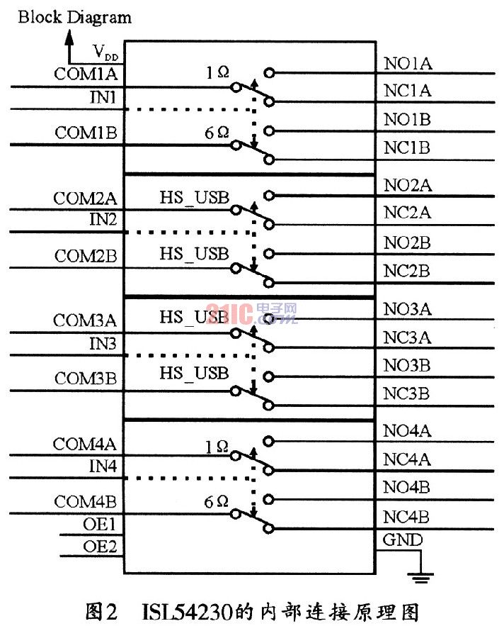
ISL54230 switch chip adopts TQFN small package, and its pin arrangement is shown in Figure 1. Figure 2 shows its internal connection function diagram. The functions of each pin of the chip are as follows:
OE1, OE2: enable control terminals of 1, 2 channel switches respectively;
IN1 ~ IN4: input selection terminals of l ~ 4 channel switches;
COM_lA, COM_2A: the common A terminal of HS switch channel 1 and channel 2 respectively;
COM_1B, COM_2B: the common B terminal of channel 1 and channel 2 of HS switch respectively;
COM_3A, COM_4A: the common A terminal of 6Ω switch channel 3 and channel 4 respectively;
COM_3B, COM_4B: the common B terminal of 1Ω switch channel 3 and channel 4 respectively;
NC_1A (B) ~ NC_4A (B): 8 normally closed switches;
NO_1A (B) ~ NO_4A (B): 8 normally open switch terminals;
VDD: power port;
GND: Ground terminal.
3 Application of ISL54230 ISL54230 is a multi-protocol switch, which contains 8 switches, which can be configured as four double-pole double-throw switches. Each of its double-pole double-throw switches can be controlled by a separate logic pin. ISL54230 has four switches, which can transfer analog or digital audio signals through USB2.0 interface. The FSL54230 is available in a 36-ball WLCSP package and a 32-pin TQFN package, and can be used in small-sized applications such as mobile phones and PDAs. Figure 3 shows the typical application circuit of ISL54230.

3.1 Switch control ISL54230 contains four switches, which can transmit analog / digital signals at full speed and high speed through USB2.0 interface mode. The USB switch can transmit high-bandwidth USB standard signals (480 Mbps) with minimal waveform and phase distortion. Among them, the 1 Ω switch is an ideal switch for transmitting 8 MHz bandwidth signals. Because its switch impedance is very low, it can greatly reduce power consumption; and the 6 Ω switch is the best choice for transmitting audio or data signals. Its bandwidth is up to 100 MHz. At the same time, it can maintain low RON THD performance.
In addition to using four independent logic control pins to control each double-pole double-throw switch, the ISL54230 also contains two OE logic pins. Through the control of the OE pin, it can provide users with a highly flexible signal routing switch. In addition, when the power supply voltage range is 2.7 ~ 3.6 V, the pin logic 0 of the ISL54230 should be less than 0.5 V voltage, and the pin logic l should be greater than 1.4 V. Therefore, all 1.8 of the chip V logic pins are compatible to +3.3 V power supply.
3.2 Power-on sequence and reset protection ISL54230 can work at a power supply voltage of 2.0 to +5.5 V, and for USB applications, the power supply voltage range should be +3.0 to +5.5 V, to Make sure the appropriate signal level of the USB cable. In addition, a decoupling capacitor of 0.01 to 0.1 μF should be connected to the working power pin of the circuit to filter out power supply noise.
Proper power-up sequence can protect the ISL54230 from failure. The ISL54230 integrates a power-on reset (POR) circuit to prevent the power supply voltage from opening the circuit switch before reaching 1.4 V. In fact, ISL54230 has a 100 mV hysteresis, so ISL54230 closes the circuit only when the supply voltage drops below 1.3 V. The hysteresis function can prevent the input signal of the switch from reaching the reset condition before the output signal is transferred to the output device, thereby ensuring the integrity of the switch signal.
The reset circuit also protects the switch when the IC voltage drops below the reset threshold. Therefore, it is recommended that the power supply voltage range of the circuit is +2.0 to +5.5 V. Although the device can still work at a power supply voltage of 2.0 V, the noise tolerance between the reset threshold and the power supply voltage will be Will decrease. In this way, the transient voltage may trigger a reset and cause the device to shut down unexpectedly.
3.3 Overvoltage and overcurrent protection ISL54230 has overvoltage protection function. The device contains an ESD protection diode, which provides a bias path from end point to ground. When the negative pressure on the port of the switching device is large, these diodes can discharge a large ESD current, thereby playing the role of ESD protection. Therefore, the signal on the ISL54230 port should not be negative pressure, that is, the "absolute maximum rating" of the ISL54230 cannot be exceeded.
When the power supply voltage of ISL54230 is less than 5.5 V permitted by the ESD protection circuit. Its transmission signal is higher than +5.5 V without much adverse effects. The ISL54230's ESD protection function allows the signal voltage to exceed the working power supply VDD, it does not induce a large current on the switching circuit, so this function is suitable for USB2 .Short-circuit protection from 5.25V Vbus short-circuit line to USB signal line in 0 mode.
It should be noted that when the power supply voltage is higher than the reset threshold and VBUS fails, if the logic control pin is set to the on state. Then, the VBUS signal will be passed to the other ports of the switch.
3. 4 USB switch designs The four USB FS and HS switches of ISL54230 are bidirectional analog switches, which can transmit signals rail-to-rail with minimal distortion. For a 3.0 V power supply, these switches have a signal range of OV to 400 mV at a nominal impedance of 6 Ω. The low capacitance and high bandwidth make it ideal for USB applications. They are specially designed to transmit USB FS (12 Mbps) and USB HS (480
Mbps) for differential signals.
3.5 Design of logic control pins ISL54230 has six logic control pins such as OE1, OE2 and IN1 ~ IN4. IN1 ~ IN4 can independently control each double-pole double-throw switch and two OEX enable pins. These logic control pins can determine the state of this switch. The truth table of OE control pins is listed in Table 1. Table 2 is its input selection truth table. These two tables give the ISL54230 pin switch control operation method.
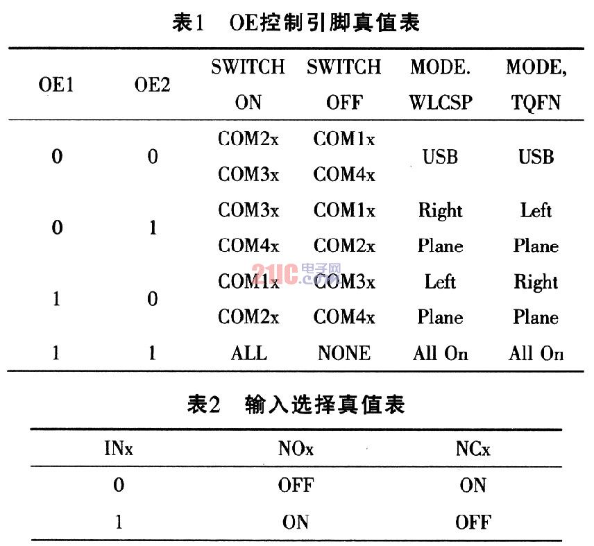
When the OEx control pin is at a logic low level, the switch is in the switch trigger state under the control of IN2 and IN3 under COM2x and COM3x, respectively. When the OEx control pin is at a logic high level, all switch states trigger the switch state under the control of INX. The status of other switches can be set as an example and according to Table 1 and Table 2.
The logic control level of ISL54230 is as follows:
When VOEx≤0.5 V, OEx is "0" (low level);
When VOEx ≥ 1.4 V, OEx is logic "1" (high level);
When VINx≤0.5 V, INx is logic "0" (low level);
When VINx ≥ 1.4 V, INx is logic "1" (high level).
4 Conclusions Each DPDT switch unit of ISL54230 can be independently controlled with logic input signals. This flexible configuration method can switch and route the USB, UART, PCM of the Bluetooth physical layer, SIM card power / data and audio signals between the internal chip and the external connector pins. In particular, ISL54230 allows dual baseband chips to access one of the two SIM cards,
At the same time, turn off the power of the unused SIM card to make it enter a zero power consumption state. Therefore, ISL54230 is undoubtedly the ideal switch connection device for mobile phones.
PVC Fire resistant cables(Wires) are coated with a self developed fire retardant (FR) pvc compound that halts the spread of fire even in extreme temperature cases. The compound also offers a high dielectric strength and high insulation. Fire-resistant cable can still ensure the normal operation of lines within certain time in case of combustion. It is different from the ordinary flame retardant cable in that in the event of a fire, it may continue electricity transmission. The use of this product will allow high-rise buildings, subways, power plants and other major occasions to have better fire safety and fire rescue capability.

Advantages:
- High Insulation
- Longer flex life
- Excellent electrical properties
- Chemical & acid resistance
- Large tensile strength
- Good softness
- Excellent elasticity and stickiness

Standard:
GB/T19216.21

Rated Voltage:
450/750V
Application:
This cable is designed for areas where the integrity of the electrical circuit is critical in maintaining power supply. Applications can be found in emergency lightings, control and power circuits, power stations, fire alarm systems, underground tunnels, communication systems, sewage treatment plants, lifts, escalators and high-rise buildings
Welcome to visit our factory to learn more about us. If you have any questions, please feel free to contact us.
PVC Insulated Fire Resistant Wire
PVC Insulated Fire Resistant Wire,Fire Resistant Cable,Heat Resistant Electrical Wire,Fire Resistant PVC Insulated Copper Wire
Smartell Technology Co.,Ltd , http://www.liencable.com