The door system that has been mechanically controlled has gradually changed to electronic control. More and more low-end cars have begun to adopt electronically controlled door control systems, using CAN or LIN bus communication technology to achieve communication between the four doors. The window anti-pinch function is one of the difficulties of the door control system. The door control system has a variety of fault diagnosis capabilities, which can identify short-circuit, open circuit, overheat, overload and other faults in time.
This article refers to the address: http://
This paper combines the project practice of car door control module design, focusing on the hardware and software design of the electric window part. The startup characteristics and fault detection characteristics of the intelligent power chip BTS7960 during normal operation were studied and analyzed, and the test results were given.
Overall design of the door control module
Figure 1 is a block diagram of the gate module, in which the microcontroller XC164CS is used to control the switching action of all power devices, while timing monitoring the system status, receiving appropriate fault feedback signals, and implementing through the vehicle network (such as CAN bus) The exchange of fault information and button control information with the central body controller and other door controllers enables timely display of fault content on the user interface and real-time control of the doors to ensure driving safety.
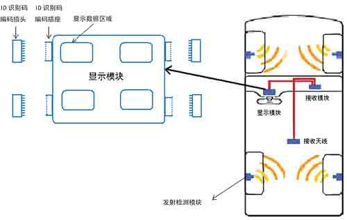
Figure 1 Overall control block diagram of the gate module
The 16-bit microcontroller XC164CS is based on the enhanced C166S V2 architecture, combining the advantages of RISC and CISC processors, and powerful computing and control capabilities through the DSP functionality of the MAC unit. The XC164CS integrates a powerful CPU core with a complete set of powerful peripheral units on a single chip, making the connection very efficient and convenient.
The electric window adopts two half-bridge intelligent power drive chips BTS7960B to form an H-bridge drive. The drive chips of the central door lock, mirror and heater are TLE6208-3G, BTS7741G and BSP752R respectively, and the driving chip of the lamp is BTS724. . These devices have provided comprehensive fault detection and protection, thus avoiding the use of excessive discrete components, greatly reducing module size and improving the EMC (electromagnetic compatibility) of the module.
The circuit of the door control module is mainly composed of the following parts: power supply circuit, electric window drive circuit, rear view mirror drive circuit, heater drive circuit, central door lock drive circuit, lamp drive circuit, CAN bus interface circuit and button interface Circuits, etc.
Hardware design of electric windows
1 electric window drive circuit and starting characteristics
The window control system drives the DC motor to rotate through the intelligent power chip BTS7960. The interface circuit of the BTS7960 is shown in Figure 2. Pins 7960INH1, 7960IN1, 7960IS1, 7960INH2, 7960IN2, and 7960IS2 in the figure are connected to I/O ports P9.4, P1L.4, P5.6, P9.5, P1L.5, and P5.7 of the XC164CS, respectively.
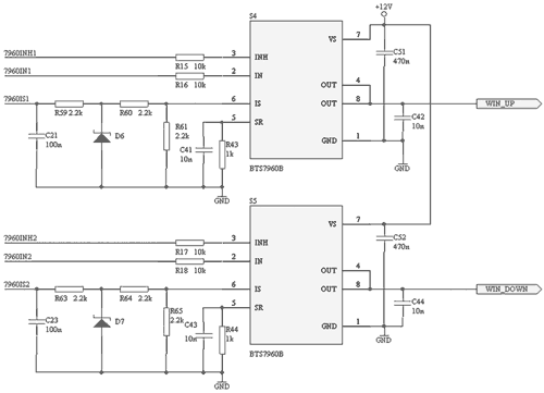
Figure 2 BTS7960 interface connection diagram
The BTS7960 is a high current half-bridge high-integration chip for motor drive with a P-channel high-side MOSFET, an N-channel low-side MOSFET, and a driver IC. The P-channel high-side switch eliminates the need for a charge pump and thus reduces EMI. The integrated driver IC features logic level input, current diagnostics, slope regulation, dead time generation, and overtemperature, overvoltage, undervoltage, overcurrent, and short-circuit protection. The BTS7960 on-state resistance is typically 16mΩ and the drive current is up to 43A. Therefore, even in the cold winter in the north, the safe start of the window can be guaranteed.
As shown in Figure 3, the two BTS7960s form a full bridge drive window that rises or falls. When T1 and T4 are turned on, the window rises; when T2 and T3 turn on, the window drops. The system does not have an active braking process. After the window is moved, the upper tube trigger signal stops, and the anti-parallel diode continues to flow through the lower arm of the bridge arm until the current is 0A. The freewheeling process lasts for 250ms, which is enough to meet the high power requirements of the window motor. In order to avoid the current spike at the moment of starting the window motor, the soft start function is realized by controlling the PWM signal of the frequency of 20 kHz to the lower arm switch tube.
2 BTS7960 fault detection characteristics
As shown in Figure 3, the chip inside the BTS7960 is a half bridge. The INH pin is high to enable the BTS7960. The IN pin is used to determine which MOSFET is turned on. When IN=1 and INH=1, the high-side MOSFET turns on and the OUT pin outputs a high level; when IN=0 and INH=1, the low-side MOSFET turns on and the OUT pin outputs a low level. The size of the external resistor of the SR pin can adjust the time when the MOS transistor is turned on and off, and has the function of preventing electromagnetic interference. The IS pin is the current sense output pin.
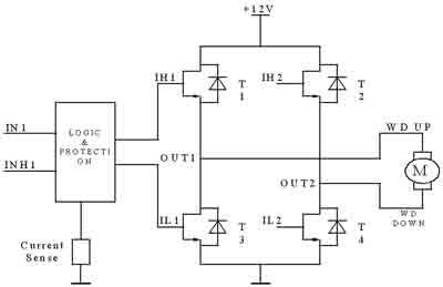
Figure 3 Schematic diagram of the full bridge drive circuit
The pin IS of the BTS7960 has a current sense function. In normal mode, the current flowing from the IS pin is proportional to the current flowing through the high-side MOSFET. If RIS = 1kΩ, V IS = I load / 8.5; under fault conditions, the current flowing from the IS pin is equal to I IS(lim) (about 4.5mA), the final effect is that IS is high. As shown in Figure 4, Figure (a) shows the IS pin current output in normal mode and Figure (b) shows the current output on the IS pin under fault conditions.
The experimental conditions of the BTS7960 short-circuit fault test are as follows: +12.45V battery voltage, +5V power supply, 2.0m short-circuit wire (R=0.2Ω), cross-sectional area of ​​0.75 mm, connection of 1kΩ resistor and one LED. The length between the VS and the positive electrode of the battery is 1.5 m (R = 0.15 Ω). As shown in Figure 5, where V IS is the voltage from the IS pin to ground, VL is the OUT pin to ground voltage, and IL is the short circuit current flowing through the BTS7960 when a short to ground fault occurs.
(a) (b)
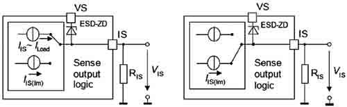
Figure 4 BTS7960 current detection pin IS working principle diagram
Whether it is short-circuited after power-on or short-circuited after first short-circuiting, the BTS7960 exhibits the same protection characteristics, so only one of them will be described below.
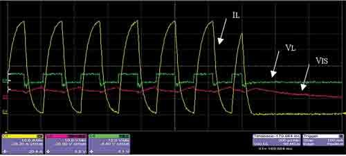
Figure 5 BTS7960 short circuit test circuit diagram
Fig. 6 and Fig. 7 are the first half and the second half of the waveform diagram of the power-on short circuit after the BTS7960 is short-circuited first. When the short circuit occurs, the current at the output terminal rises rapidly. In the time of 80μs, the current rises to the peak value, which is about 62A. At this time, the BTS7960 detects a short-circuit fault, turns off the MOS transistor, and the output current drops to 0A. The portion indicated by the purple arrow has obvious turn-off. The portion enclosed by the dotted line in the figure is the process of turning off and maintaining the turn-off of the MOS transistor. The entire process lasts approximately 80 μs. When the short circuit is turned on, the output voltage of the OUT pin is about 5V, which is the voltage dividing value of the total resistance between the short-circuit wire and the battery and the ground; during the turn-off of the MOS transistor, the output voltage of the OUT pin is 0V. At the moment when the current drops sharply, a weak back electromotive force is induced on the short-circuiting wire, so the output voltage of the OUT pin exhibits a short-time negative voltage. The state detection pin IS fluctuates up and down around 5V, and it has the characteristics of fluctuating up and down with the short-circuit current. During the entire short circuit, the BTS7960 periodically turns off the MOS transistor to prevent the short-circuit current from continuously heating up the chip, causing the chip to overheat and burn, thus effectively protecting the chip. Finally, the BTS7960 completely turns off the MOS transistor, and the short-circuit current is ramped down to 0A. The IS pin is restored to its normal level by its own cooling for about 500μs after the MOS transistor is completely turned off.
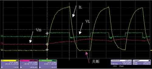
Figure 6 BTS7960 short circuit experiment waveform diagram first half

Figure 7 BTS7960 short circuit experiment waveform second half
Software design of electric windows
1 driver chip BTS7960 software design
In the electric window part, the BTS7960 drives the DC motor to rotate, so that the window rises or falls. Two pieces of BTS7960B are used to form a full bridge.
The interface signals of the BTS7960 and the microcontroller include IN1, IN2, INH1, and INH2; IS1 and IS2 are current sense signals.
The window is raised: IN1=1, IN2=0, INH1/2=1; the window is lowered: IN1=0, IN2=1, INH1/2=1.
The whole driving process can be divided into four stages: soft start, full PWM output, freewheeling and stop. The window lifting process realizes the soft start function by PWM control of the lower arm switching tube. The PWM frequency is 20 kHz and the soft start lasts for 200 ms. In this process, the duty ratio gradually increases from 0% to 100%. Divided into 10 segments, each segment lasts for 20ms. The PWM signal is applied to the INH pin of the bridge arm where the lower leg is located. When the bridge arm is turned off (INH = 0), current flows through the reverse diode of the upper tube. After the soft start is realized by the PWM signal, the current waveform when the power window is started is as shown in FIG. 8. As can be seen from the figure, the current spike is effectively suppressed.
There is no active braking process in this system. After the window is moved, the switch tube will work for about 250ms. This is the freewheeling process. During this period, the upper tube trigger signal stops, and the anti-parallel diode continues to flow through the lower arm of the bridge arm. At the same time, it is necessary to continue to give the lower tube trigger signal of the other bridge arm, such as positive freewheeling: IN1=1, INH1=0, IN2=0, INH2=1) until the current is 0. But if there is overheating, this freewheeling process is not needed.
Motor stalling is not allowed because of the overcurrent. The BTS7960 itself can detect the current of the switch tube and perform current/voltage conversion through a 2.2kΩ sample resistor current. The sampled voltage is passed through a simple RC filter network and sent to AN0/AN1 for analog-to-digital conversion via a protective resistor (not added). When the current is detected to be greater than 15A, it can be judged that the motor is in a stalled state. At this time, the microcontroller stops triggering the motor (still need to be freewheeled), and the user can restart the window.
The fault to be detected in the window part is that the two switching tubes of the upper arm are overheated and the load is open. The first method is to detect the overheating of the upper tube through the built-in temperature detection function of the BTS7960. When the overheat occurs, the device automatically turns off all output circuits, and the output level of the IS pin is high. Second, the auxiliary transistor is required to detect the open circuit, and the IS is detected. The pin current value can be implemented and requires the microcontroller to provide the CTRLWIN signal.
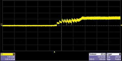
Figure 8 Power window soft start current waveform
2 Software design of the main program of electric window
The software control of the power window control system is based on state transition. By comparing the system state with the control command to make a judgment, determine the action that the current system should perform. In the program, the operating state of the power window is divided as follows: WINDOW_OFF, WINDOW_UP_PWM, WINDOW_UP, WINDOW_UP_FREE, WINDOW_UP_STOP, WINDOW_DOWN_PWM, WINDOW_DOWN, WINDOW_DOWN_FREE, and WINDOW_DOWN_STOP. When the power window is in the OFF state and receives a command to rise or fall, the program will cause the window to enter the PWM increasing state first to achieve a soft start. When the PWM full duty cycle is reached, the window will go into the UP or DOWN state. If you receive a command to stop the power window or turn it in the opposite direction while the PWM is increasing or PWM full duty, the program will let the window enter the freewheeling state. The freewheeling is completed and the window enters the STOP state. In any state, if an open circuit or overvoltage fault is detected, the window will enter the OFF state.
Bluetooth speaker,Portable bluetooth speaker, wireless protable outdoor speaker
SHENZHEN YINZHIGUAN DIGITAL TECHNOLOGY CO.,LTD , http://www.yzgmusiccrown.com