The advantage of a projection display is its flexible physical specifications. An early example of this flexibility occurred in 1942, when the Royal Air Force created the first "head-up display" (HUD) that allowed pilots to see radar information directly within sight. This design milestone takes advantage of one of the basic features of a projection display, the ability to convert almost any surface into a display. In addition, it can create large images with a small size, indicating that the projection display can have a significant impact. These features combine to transform the concept of "display" from a stand-alone component to an integrated feature that can be integrated anywhere on demand, indicating that projection displays will bring many possibilities.
Although this military display example was introduced decades ago, until recently, with the commercial use of microdisplays and solid-state lighting sources, manufacturers were able to fully realize the potential of projection displays in a wide range of industrial applications. Applications such as home automation, digital signage, human machine interface (HMI) / immersion technology benefit from a real-world technology that can be hidden when not in use, transforming any size or shape of the surface into a display, if needed It can even be turned into an interactive display. Similarly, near-eye displays require high-quality display technology that can be adapted for compact industrial designs.
For today's developers, brands, and system integrators, incorporating projection technology into emerging and existing industrial products requires three basic steps: determining critical projection requirements, choosing the right projection technology, and choosing a supply chain.
Requirements-balance exerciseBalanced advantages (characteristics and functions) and limitations (cost, size, weight, energy consumption, etc.) are key to successful product development. The first step in achieving this balance is to understand the basic requirements. For projection displays, this means understanding the resolution, color gamut, brightness and contrast required. Therefore, the focus of this article is to introduce some design considerations as a step in determining the necessary requirements for integrating pico projection into industrial display applications.
Technology - the feast of choiceToday's designers can choose from three projection display technologies: 2D MEMS arrays, scanning mirrors (both single and dual), and LCD/LCoS. The technology that best suits your particular application depends on the specific product requirements. This article will review each technology and explore resolution, color gamut, brightness, and contrast.
Supply chain - the last step that is crucialIf you can't put it into production, then the most elegant design is worthless. Therefore, in addition to processing the right projection technology, designers must also consider the available supply chain. This article does not provide a detailed supply chain analysis, but the factors that should be considered include the availability of finished solutions, custom design opportunities, delivery times, and technical support.
Required resolution - look closelyThe resolution acuity of the Human Vision System (HVS) is a very useful roadmap that can be used to determine the resolution required for a given display system.
A normal observer can resolve 50 line pairs per arc, and a line pair contains black lines adjacent to the white line, thereby forming a high contrast characteristic. This leads to the following relationship:
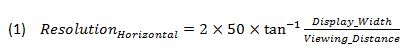
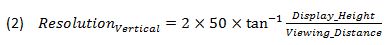
Determining projector resolution requirements with these formulas depends on how the display is used. For example, these formulas directly determine the target resolution of an interactive display, viewing the entire display at a time. However, for an on-demand display, the information only covers a portion of the projected display area at a time, requiring a higher projection resolution.
Resolution and technology2D MEMS and LCoS/LCD have been widely used in common video and graphics resolutions (VGA, XGA, WXGA, 720p, 1080p, etc.).
In theory, scanning mirror technology can create any desired resolution. In practice, the resolution is limited by the laser spot size (the smaller the spot size, the higher the resolution limit), assuming that both the mirror scan rate and the laser pulse rate are sufficiently high. In addition, the laser spot size is a function of beam quality (M2), and the higher the beam quality, the higher the cost.
Required color - wide selectionFor the first order, the display system produces colors in a manner similar to the HVS perceived color. The human eye contains three color receptors (cones), each of which responds to a different wavelength range. These wavelength ranges are roughly equivalent to red, green, and blue. Projection displays use a mixture of red, green, and blue primary colors in a similar manner to produce a wide range of color choices.
There are many factors that affect the quality of the colors reproduced on the screen. The light engine's factors include the color gamut it can produce, depending on the saturation of the primary colors. In fact, the laser produces the highest saturation, followed by the LED, followed by the filtered white light source (such as a light or white LED).
The 1976 CIE Chromaticity Diagram (Figure 1) helps to visualize the gamut range. In the figure, the outer curve boundary (spectral track) represents the full range of visible monochromatic light, and the points in the figure represent all colors that the HVS can perceive.
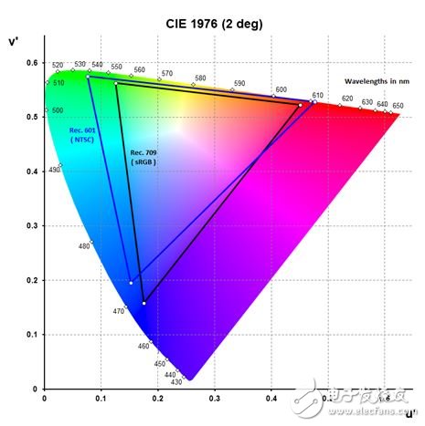
Figure 1 – CIE u'v' Chromaticity Diagram
Various standard color gamuts have been specified, such as the Rec.601 (NTSC) and Rec.709 (sRGB) color gamuts (Figure 1). These color gamuts are useful reference points for conveying the relative color of the display system gamut. A common way is to calculate the area of ​​the display gamut triangle (in the u'v' space) and the ratio to a particular standard gamut triangle. For example, the "70% NTSC" color gamut is sufficient to make a quality display, while the 100% NTSC color gamut provides a better perceived color.
In addition to color gamut, factors to consider when selecting a light source include cost, size, power consumption, and compatibility with selected display technologies. For this discussion, we will focus on the latter.
Color and technologyThe developer should first consider the target color gamut, then consider the light source needed to implement the color gamut, and finally consider the compatibility between the light source and the projection display technology.
2D MEMS and LCD/LCoS devices can be combined with any light source (LED, laser, lamp) currently available. Therefore, each technology can achieve a similar color gamut. The difference lies in the achievable system optical efficiency. This issue will be discussed in the "Brightness" section.
Scanning mirrors require single-mode laser illumination; therefore they can achieve very large color gamuts. However, it is also necessary to consider the secondary effects of speckle and the cost of the laser.
The required brightness - how bright is enough?The brightness of a display is usually quantified in a number of ways: lumens and nits. Lumens (candela* steradian) is the SI unit of luminous flux and represents the total amount of light emitted from the display. Nit (Candela / square meter) is a measure of brightness (per solid angle, light energy per projection source area), related to perceived brightness.
Users won't discuss it from Nite's point of view, but Nite is what they experience: the brightness emitted (or reflected) from the display area. Since projector manufacturers usually do not control the display, they usually illuminate the lumen output of the light engine.
Table 1 provides some nit reference points.
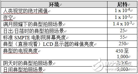
Table 1 – nit reference points
Once the brightness (Nit) requirements are determined, the required screen gain and system optical efficiency can be determined based on the following relationships:
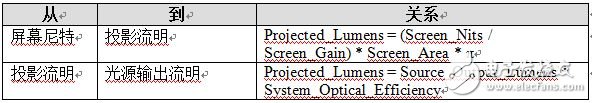
Screen gain is a feature of screen design. The screen with a gain of 1 has two unique features. First of all, it is a Lambertian type, which means that the brightness seems to be the same from all viewing angles. Second, it did not absorb. By reducing the screen absorption and/or redirecting more light to the on-axis viewing angle, the screen gain can be increased (which means that the screen appears brighter to the viewer of the on-axis angle).
The system light efficiency represents the transmission efficiency of the output from the light source to the last optical component. For 2D MEMS or LCoS/LCD panels, the last optical component may be part of the projection lens. For a scanning mirror, the last optical component may be the mirror itself.
Brightness and technologyScreen gain is independent of projection technology, but the optical efficiency of the component is closely related to projection technology, as it depends on the specific light engine design, and the architecture of each technology light engine design is completely different.
In terms of optical efficiency, there are four component-level factors: reflection loss, absorption loss, diffraction loss, and geometric loss. The reflection loss includes the loss of light reflected at each optical interface, and the reflection loss can be almost completely eliminated with the anti-reflection coating.
Absorption loss refers to light that is absorbed by the loose material of each optical component, which is very rare for optical materials commonly used in projectors.
The diffraction loss is derived from the nature of the light wave, causing the light to shift when it encounters edges and small objects, where "small" is based on the wavelength order. Diffraction loss varies by technology.
Geometric loss is due to the etendue mismatch on the optical path. In projection systems, the most common geometric loss is the etendue mismatch between the source and the display panel. If the etendue of the light source is greater than the etendue of the display panel, then the display panel cannot capture all of the light produced by the light source.
Developers should try to choose a higher intrinsic optical efficiency and be able to create a display technology that minimizes the number of components and best matches the light collection of the light source.
2D MEMS offer maximum flexibility because they have good optical efficiency and are capable of matching the etendue of any source.
With LCD/LCoS, a polarized light source (laser) delivers the highest system optical efficiency. LEDs and lamps can also be used, but the optical efficiency of the system will be lower.
Scanning mirrors require highly collimated light sources and are limited by these, they can only be used with lasers.
Required Contrast - Unknown HeroContrast is the secret of a shiny display, but ironically, black is the most important color. The black quality that the display can create sets the benchmark for a variety of other intensities and colors.
The blackness of the projection system depends on two factors: the intrinsic contrast of the display system and the ambient brightness. System designers can sometimes control ambient light levels, sometimes uncontrollable (depending on the application), and the inherent contrast of an optical system depends on multiple system factors, some of which are controlled by the designer.
There are two common ways to quantify the contrast of a display system. The full-on/full-off (FOFO) contrast method, which measures the light output of all whites and all blacks, and then calculates the contrast.
The ANSI contrast method first displays the ANSI checkerboard (16 black and white patterns), first measures the brightness of all white boxes, and then measures the brightness of all black boxes. ANSI contrast is the ratio of the average of white brightness divided by the average of black brightness.
One might think that the two methods can achieve the same contrast, but this is not the case. To understand this phenomenon, you need to use "contrast" as a measure of "stray light." Then, each method is considered to measure stray light from different parts of the system. Specifically, the FOFO evaluates the stray light produced by the panel, while ANSI evaluates the stray light produced by the rest of the optical system.
Mathematical operations can lead to deeper insights. Equation 3 shows the relationship between the overall system contrast (S), the intrinsic contrast (P) of the display panel, and the intrinsic contrast (K) of the rest of the optical system.
Equation 4 can be derived from Equation 3.
(4)
Equation 4 shows that S is equal to "P multiplied by a scaling factor", where the scaling factor depends on the P/K ratio. Figure 2 shows how the system contrast (S) varies with light contrast (K), which is assumed to be convenient for convenience. Figure 2 shows that as the light contrast increases, the system contrast gradually approaches the display panel contrast. In addition, the “return point of return†is also displayed, that is, when the light contrast is 4 to 9 times the contrast of the display panel.
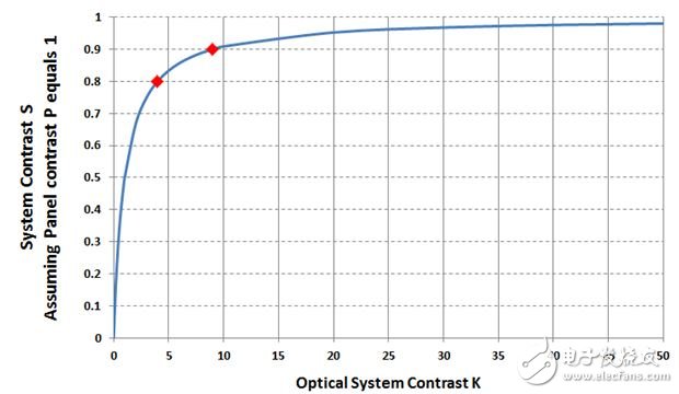
Figure 2 - System Contrast and Optical System Contrast
Equation 5 shows the effect of ambient light on the displayed contrast (CRDISPLAYED).
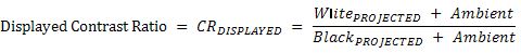
(5)
If there is no ambient light (ambient light = 0), the native projector contrast (CRPROJ_NATIVE) is used as WhitePROJECTED/BlackPROJECTED, and the following conclusions are drawn: 1) When Ambient = BlackPROJECTED, with CRPROJ_NATIVE increasing, CRDISPLAYED gradually approaches 0.5 * CRPROJ_NATIVE; 2). As Ambient gradually approaches WhitePROJECTED, CRDISPLAYED gradually approaches 2, which produces a very bad display.
Contrast and technologyIdeally, you should choose the display technology with the highest intrinsic contrast and optimize the system contrast as needed to achieve the overall target contrast.
The intrinsic panel contrast of a 2D MEMS depends on the amount of light that is emitted from the MEMS structure. Designing the optical system to use a larger (slower) aperture factor reduces light scattering and, in addition, reduces the size of the system optics and reduces its cost, but at the expense of some brightness.
The inherent contrast of the LCD/LCoS is basically dependent on whether the panel can fully rotate the light polarization to the "off" position, which is a function of the panel design.
The contrast of the scanning mirror is closely related to whether the laser-driven electronics can completely turn off the laser.
ConclusionThis article explores requirements for display resolution, color gamut, brightness, and contrast. In addition, it is discussed whether the currently available display technologies can meet these requirements.
Scanning mirror displays achieve higher resolution, color gamut, brightness, and contrast by using a laser, but at the expense of sacrificial spots, and the cost of the laser is higher.
The LCD/LCoS display achieves higher resolution with the inherent resolution of the display panel, and the color gamut is obtained from the light source (LED, laser, lamp). The brightness depends on the efficiencies that the optical system design can achieve, and when using LEDs and lamps, it is limited by the chosen polarization technique. The contrast depends on whether the panel is able to fully rotate the light polarization to the "off" position.
2D MEMS displays achieve higher resolution with the inherent resolution of the display panel, while 2D MEMS panels provide common resolutions (VGA, XGA, WXGA, 720p, 1080p, etc.), obtaining color from light sources (LEDs, lasers, lamps) area. Again, the brightness of the display is based on the efficiency of the optical system, but without polarization limitations. The intrinsic contrast of 2D MEMS stems from the scattering of MEMS structures, which can be reduced by the larger (slower) aperture light design. A very unique feature of today's leading 2D MEMS technology is the ability to use data processing techniques to enhance perceived brightness and contrast, or to reduce power consumption.
Low Rate Nicd Battery KPL Series
Established in 1956, during the China first five-year-plan, Henan Xintaihang Power Source Co., Ltd. (Factory No.755) was the first R&D and manufacturing enterprise in China in the field of alkaline storage batteries and modular power system and it was also the military factory which owned the most varieties rechargeable batteries in domestic. Taihang was located in national Chemistry and Physicals Power Source Industrial Park, Xinxiang City, Henan, China.
Low Dishcharge Rate Nickel Cadmium Battery, KPL10~KPL1200, Max. discharge current <0.5C.
The nickel–cadmium battery (NiCd battery or NiCad battery) is a type of rechargeable battery using nickel oxide hydroxide and metallic cadmium as electrodes. The abbreviation NiCd is derived from the chemical symbols of nickel (Ni) and cadmium (Cd).
Ni Cd Battery,110V Kpl 300Ah Battery,Kpl1000Ah Nicd Battery,Low Rate Nicd Battery Kpl Series
Henan Xintaihang Power Source Co.,Ltd , https://www.taihangbattery.com