The high reliability of LEDs (lifetime exceeding 50,000 hours), high efficiency (> 120 lumens / watt), and near-instantaneous response capabilities make it an extremely attractive light source. Compared with the response time of the incandescent bulb of 200mS, the LED will emit light in a short response time of 5nS. Therefore, they are now widely used in brake lights in the automotive industry.
Drive LED
Driving LEDs is not without its challenges. Adjustable brightness requires a constant current to drive the LED, and the current must be kept constant regardless of the input voltage. This is more challenging than simply connecting the incandescent bulb to the battery to power it.
LEDs have forward VI characteristics similar to diodes. Below the LED turn-on threshold (the white LED turn-on voltage threshold is approximately 3.5V), the current through the LED is very small. Above this threshold, the current will increase exponentially in the form of forward voltage. This allows the LED to be typed as a voltage source with a series resistance, with a warning note: this model is only valid at a single working DC current. If the DC current in the LED changes, then the resistance of the model should also change to reflect the new operating current. At large forward currents, power dissipation in the LED will heat the device, which will change the forward voltage drop and dynamic impedance. It is very important to fully consider the heat dissipation environment when determining the LED impedance.
When driving an LED through a buck regulator, the LED often conducts the AC ripple current and DC current of the inductor according to the selected output filter arrangement. This will not only increase the RMS amplitude of the current in the LED, but also increase its power consumption. This can increase the junction temperature and have an important impact on the life of the LED. If we set a 70% light output limit as the lifetime of the LED, the lifetime of the LED will be extended from 15,000 hours at 74 degrees Celsius to 40,000 hours at 63 degrees Celsius. The power loss of an LED is determined by multiplying the LED resistance by the square of the RMS current plus the average current by the forward voltage drop. Since the junction temperature can be determined by the average power consumption, even a large ripple current has little effect on power consumption. For example, in a buck converter, the peak-to-peak ripple current equal to the DC output current (Ipk-pk = Iout) will increase the total power loss by no more than 10%. If the loss levels above are far exceeded, then the AC ripple current from the power supply needs to be reduced in order to keep the junction temperature and operating life constant. A very useful rule of thumb is that every time the junction temperature decreases by 10 degrees Celsius, the semiconductor lifetime will increase twice. In fact, due to the suppression effect of the inductor, most designs tend to have lower ripple current. In addition, the peak current in the LED should not exceed the maximum safe operating current rating specified by the manufacturer.
Analysis of the selection of topology structure of LED drive power
In LED lighting applications using AC-DC power supplies, the building blocks of power conversion include discrete components such as diodes, switches (FETs), inductors and capacitors and resistors to perform their respective functions, and pulse width modulation (PWM) regulators to control Power conversion. The isolated AC-DC power conversion that usually incorporates a transformer in the circuit includes topologies such as flyback, forward, and half-bridge. See Figure 3, where the flyback topology is the standard choice for low and medium power applications with power less than 30 W. The half-bridge structure is most suitable for providing higher energy efficiency / power density. As far as the transformer in the isolation structure is concerned, its size is related to the switching frequency, and most isolated LED drivers basically use "electronic" transformers.
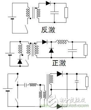
Figure 1: LLC half-bridge resonant topology
In LED lighting applications that use DC-DC power supplies, the LED drive methods that can be used are resistive, linear regulators, and switching regulators. The basic application diagram is shown in Figure 4. In the resistive drive method, the forward current of the LED can be controlled by adjusting the current detection resistor connected in series with the LED. This drive method is easy to design, low in cost, and does not have electromagnetic compatibility (EMC) problems. (Binning) LED, and low energy efficiency. The linear regulator is also easy to design and has no EMC issues. It also supports current stabilization and overcurrent protection (fold back), and provides an external current set point, which is insufficient for power dissipation issues, and the input voltage should always be higher than the forward Voltage, and energy efficiency is not high. The switching regulator continuously controls the on and off of the switch (FET) through the PWM control module, thereby controlling the flow of current.

Figure 2: Common DC-DC LED driving methods
The switching regulator has higher energy efficiency, has nothing to do with the voltage, and can control the brightness. The disadvantage is that the cost is relatively high, the complexity is also higher, and there are electromagnetic interference (EMI) problems. Common topologies of LED DC-DC switching regulators include different types such as buck, boost, buck-boost, or single-ended primary inductance converter (SEPIC). Among them, the step-down structure is adopted when the minimum input voltage is greater than the maximum voltage of the LED string under all operating conditions, such as using 24 Vdc to drive 6 LEDs in series; in contrast, when the maximum input voltage under all operating conditions is less than the minimum output voltage Boost structure, such as using 12 Vdc to drive 6 LEDs in series; when the input voltage and output voltage range overlap, buck-boost or SEPIC structure can be used, such as 12 Vdc or 12 Vac to drive 4 LEDs in series However, the cost and energy efficiency of this structure are the most unsatisfactory.
The method of directly driving LEDs using AC power has also achieved certain development in recent years. See Figure 5 for a schematic diagram of its application. In this structure, the LED strings are arranged in the opposite direction, working in a half cycle, and the LED is turned on only when the line voltage is greater than the forward voltage. This structure has its advantages, such as avoiding power loss caused by AC-DC conversion. However, in this structure, the LED switches at low frequency, so the human eye may perceive flicker. In addition, LED protection measures need to be added to this design to protect it from line surges or transients.
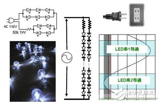
Figure 3: Schematic diagram of directly using AC to drive LED
96 Port Fiber Optic Patch Panel is provides a centralized location to manage network connections.It is suitable for different adapter (like SC simplex, SC duplex, LC duplex, ST simplex, FC simplex etc ). Not only does it provide physical security for sensitive network connections, it also promotes better organization.96 Port Fiber Patch Panel an integrated unit for fiber management, these equipment function is to fix and manage the fiber optic cables inside the box as well as provide protection. 96port Fiber Patch Panel application in Telecommunication,fiber optic communication system,FTTH,FTTX access network based on PON structure etc.
96 Port Fiber Patch Panel
96 Port Fiber Patch Panel,96 Port Fiber Optic Patch Panel,Fiber Optic Patch Panel 96 Port
Foclink Co., Ltd , https://www.scfiberpigtail.com